
Orizuru Room was a part of a TouchDesigner hackathon at the art event "Manazuru Jack Installation". Manazuru is a port town about 100km to the west of Tokyo, and during this event, many places in the town are "jacked with art works".

Concept
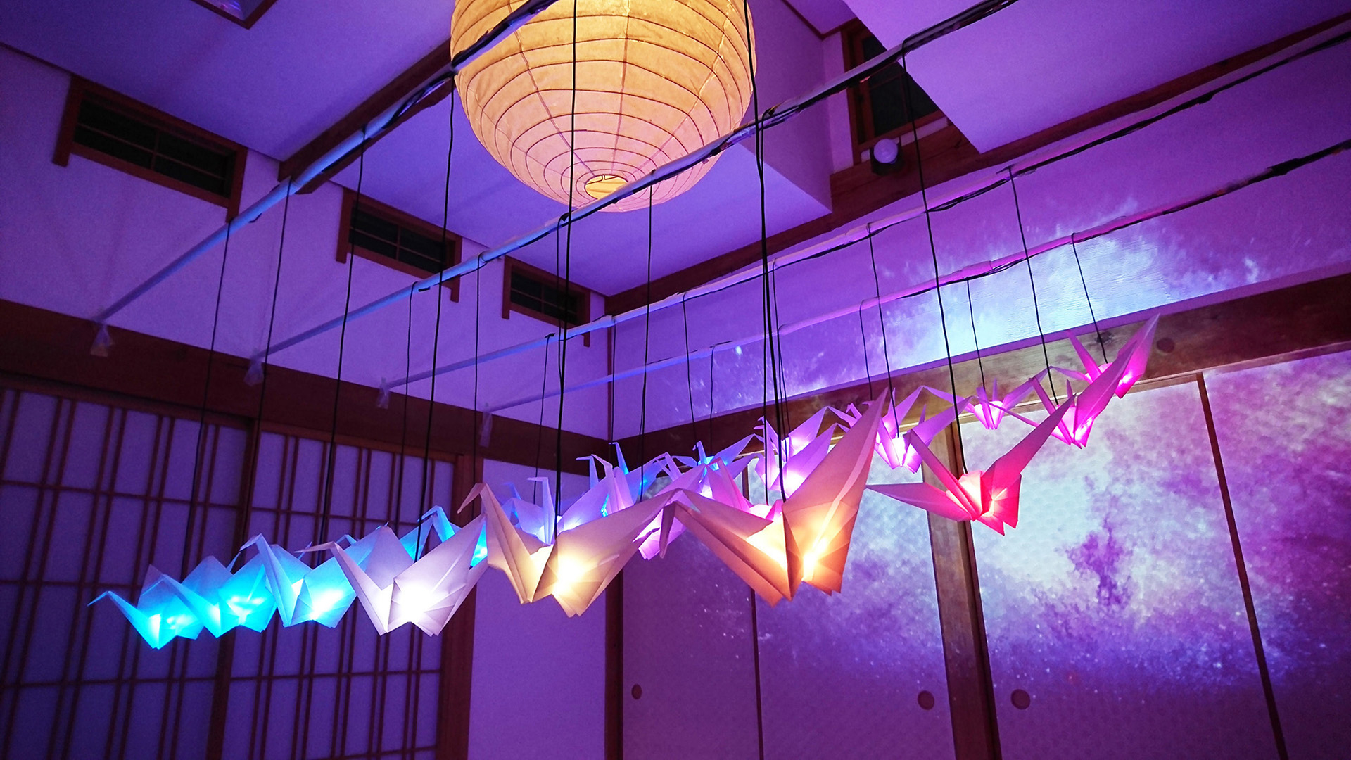
Manazuru was named after a crane due to the fact that its shape on a map very much resembles a crane. Our goal was making an installation that symbolized Manazuru, so we decided to feature origami cranes for our art work. We placed importance in collaborating on this project with locals in Manazuru and so we asked the Orizuru Association and a grand master to support us and we made origami cranes together. "Orizuru" means a crane made with origami.
Simulation
The quality of origami paper used would very much affect the overall visual of our installation an so we tested many papers of varying texture and thickness. We were looking for a material that was durable but also translucent and so decided upon a thick stock of translucent drawing paper. And we did some previsualization with a 3D software to help us decide on the size of cranes and how to best display them in a traditional Japanese tea room.

Hardware
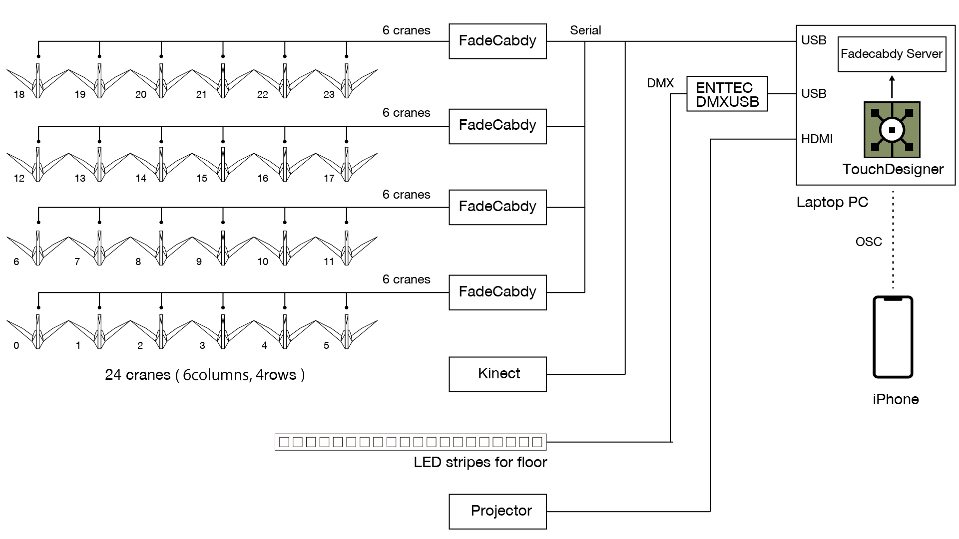
To control 24 LEDs inside the cranes through serial communication, Arduino was not performing well in FPS. So we adopted 4 Fadecandies alternatively to realize high frame rate, and spent 2 days setting up the cranes and doing the wiring and soldering.
We used a Kinect sensor to add another interactive feature to this installation whereby the cranes would brighten up when people come close to them.


Software
TouchDesigner controlled these 3 signals synchronously.
- LEDs in cranes – serial
- LED stripes on the floor edge – DMX
- Projected images on the wall – HDMI
And for maintenance and adjustment, we controlled our installation from an iPhone through OSC.
FadeCandy
This was the workflow we used to work on FadeCandy with Python scripts.
1. Download files
Here is the link for all file we used for FadeCandy.
https://github.com/JoeBeartooth/TouchDesigner_fadecandy
After downloading files, copy these 3 files into a same directory.
- fcserver.exe
- fcserver.json
- opc.py
2. Run FadeCandy server
To start FadeCandyserver, execute this command using command line tool.
fcserver.exe fcserver.json
3. Convert pixels to DAT in TouchDesigner
We placed 24 cranes in a 6x4 matrix and dealt with them like 6x4 pixels LED matrix. We imported 6x4 pixels movies in TouchDesigner and convert RGB values into a data table.

4. Sending data from TouchDesigner to FadeCandy server by Python scripts
These are Python scripts for "DAT Execute" to send data to the FadeCandy server. Reference the DAT operator in the previous step to "DAT" parameter in the dialog.

Note: If you try to work on TouchDesigner projects without starting the FadeCandy server, any action is going to be very sluggish.
fcserver.json
We made json object in reference to below. https://github.com/scanlime/fadecandy/blob/master/doc/fc_server_config.md
Here is the format for mapping objects:
[ OPC Channel, First OPC Pixel, First output pixel, Pixel count ]
We used 4 FadeCandies for 24 cranes and each FadeCandy sent data to 6 cranes. We didn't use OPC Channel, so the first element is 0. And 2nd element is the address for an LED crane, the 3rd element is the address for FadeCandy and 4th element is the number of LED pixels for one crane.

Credits
Creative Director : Atsushi Kobayashi
Technical Director : Joe Ohara
Photographer : Kenta Umeda
Specialists in Creative Direction, Technical Direction and Photography, working on interactive projects in Japan. Contact via email here.


